You know sometimes we have random thoughts and then we become curious. Take for instance, you are cruising in your car and then you take a look at your dash board to know what speed you are moving at, and then boom! A random thought flashes: how do car speedometers work? It hits at your mind so much you actually want to do a research on it. Well, it’s because of you this particular post was designed. So take a chill pill, relax and enjoy your read.

Speedometers have very simple working principles, in that they measure how fast or slow the car wheels are turning, while also calculating how big the diameter of the wheels are in relation to the speed you are driving with. Simply put, as the name implies, a speedometer is a device for measuring speed.
So the mechanism that actually takes note of the speed of your car works by activating the flexible shaft that’s driven by the gears at the end of the transmission system of the vehicle and connected to a permanent magnet that’s rotates 1,000 revolutions per mile.
This magnet also turns inside a movable metal cup that’s a non-metal, and is attached to the shaft that carries the pointer that indicates your speed. To complete this circuit, a static field plate is attached and completely surrounds the movable cups. The faster the magnet rotates, the more pull it has on the cup and the pointer.
Now if that’s too much information to take in at once, we’ll help you. It might interest you to know that there are basically two types of speedometers that cars use. They both have their working principles. We will try to break them down as much as we can so you can understand the previous paragraph better.
TYPES OF SPEEDOMETER
As earlier stated, there are two types of speedometers namely: mechanical speedometers and electric speedometers. Find below is a breakdown of how they work.
Mechanical speedometers
This is the most common type of speedometer you will see in cars until manufacturers started using the digital type in more recent models. So for mechanical speedometers, once you press the throttle or accelerator (if you like) of your car, the wheels of your car spin faster or slower, depending on how much fuel is supplied to the cylinders of the engine. Bear in mind that the amount of fuel supplied is dependent on the amount of pressure your foot applies on the accelerator of the car.
The mechanical speedometer measures speed by taking note of the number of times the car wheels’ spin and then uses the laws of electromagnetism to convert the circular motion of the wheel to the smooth ticking of the gauge inside the car. This mechanism will measure the rotation of the wheels and send a feedback to the speedometer turning the magnet.
This magnet can spin freely inside the speed cup that also rotates. The speed reading of the speedometer is detected by the speed cup connected to a coil of wire and to the gauge as well. The magnet that’s spinning in the speed cup generates a magnetic field that depends on the speed of the car and the turning of the cable.
What this leads to is that because of this turning effect and the strong magnetic field, electricity is generated. But this electricity has no direction, and this is why scientist refer to mechanical speedometers as Eddy Current speedometers. However, these electrical currents that are turning will make the speed cup rotate so it can catch up to the speed of the rotating magnet.
The coil of wire stops the speed cup from rotating as much as the magnet which then makes it pull the pointer up the display of the speedometer. So the faster the car travels, the faster this action repeats itself. But just remember it starts with you applying pressure with your foot on the throttle or accelerator.
Electric speedometers
You might not find this type of speedometer easily but they serve their purpose very well. Where the mechanical speedometer has drawbacks in inaccuracies with measurements and the normal mechanical failure, the electric speedometer makes up for it. Slowly but surely, electric speedometers are replacing the mechanical type.
The working principles of an electric speedometer is simpler than that of the mechanical type as well. The electric speedometer makes use of a speed sensor, which usually entails having a magnet that is surrounded by a wire coil just like the pickup of an electric guitar. This sensor is attached directly close to a gear on the transmission train. So as the gears rotate, the teeth of the gear move on, causing an interruption in the magnetic field of the sensor.
This is also the same way a string on the guitar vibrates and activates the pickup of the guitar. The gear movement mentioned earlier produces an electric current that is directly proportional to the rotating speed of the gear. This is where the services of a computer chip will be employed to convert the current produced into numbers that match with the speed at which the car is moving, in miles or kilometer per hour.
PARTS OF A SPEEDOMETER
I know that in passing, we have outlined most of the parts involved in how speedometers work. Whether it is the mechanical or electric speedometer, there are some parts or components that are consistent between the two of them. Some of these parts are:
The driveshaft connection
The component of a vehicle that is responsible for transferring torque and rotation to the wheels of the car is called a drive shaft. There is also a cable that connects this driveshaft to the speedometer.
It is long and twisted in nature. So once the engine of the car is cranked, the drive shaft rotates and this will in turn make the cable connecting it to the speedometer turn as well.
Magnetic spins
Having an understanding of magnets will help in understanding how speedometers work. As the speedometer cables start rotating, the magnet also starts rotating at the same exact speed of the drive shaft and the speedometer cable. The rotation of the magnet is in sync with the direction of the drive shaft and the cable.
Speed cups
This is not the first time we have mentioned a speed cup in this post. To explain it better, a speed cup is a component that is free to rotate but is kept in check by a very thin wire coil called a hair spring. The magnetic field that generates when the magnet rotates is housed in the speed cup. The magnetic field creates a current that rotates anti clockwise to match the speed of the magnet.
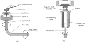
The hairspring
As mentioned earlier, the hairspring is a thin wire coil that stops the speed cup from making any movement. As the speed cups rotate anti clockwise due to the current generated from the magnets, the hair spring controls this speed. It makes sure that the speed cup does not in any way move in sync with the movement of the magnet. So as the speed cups turns with limited speed, it also pulls the pointer on the dial of the speedometer on the dash board to indicate the speed of the vehicle.
Inference
Putting all of these together, as you press the accelerator, the speed of the car increases. As this happens, it turns the drive shaft cable – thereby turning the speedometer cable as well. As the speedometer cable turns, it gives motion to the magnet which then leads to the generation of current in the speed cup. The magnitude of this current is enough to pull the pointer up the dial on the speedometer. And there you have it! You can now see the speed of the car on the speedometer.
Conclusion
Speedometers, whether mechanical or electrical have very similar working principles. But whichever it is, the goal is to show you the speed you are traveling with.

